
Oxygen FAQ
Up to date, expert answers to frequently asked questions (FAQ) about oxygen supply systems, respiratory care and pulse oximetry written by OCC & collaborators.
Oxygen Delivery Devices
- Most are not considered reusable per manufacturer specifications
- Check with the manufacturer specification and clinical guidelines to determine if reuse is safe
- Steps for disinfection must be closely adhered to and may be manufacturer specific
- Some reusable devices (e.g. some ventilator circuits) may have a finite lifespan (e.g. a predefined number of sterilizing cycles)
- Reusability of respiratory care devices is often debated and may vary based on local/national practice guidelines and regulations
Click here to review WHO tips for cleaning and disinfection of respiratory equipment
Additional resources:
- Infection Prevention and Control of Epidemic- and Pandemic-Prone Acute Respiratory Infections in Health Care (WHO)
- Disinfectants for COVID-19 (US EPA)
- Cleaning of CPAP and other devices used to administer supplemental oxygen (DPHSS Montana)
- Persistence of coronaviruses on inanimate surfaces and their inactivation with biocidal agents. G. Kampf, D. Todt, S. Pfaender, E. Steinmann. Journal of Hospital Infection 104 (2020) 246-251.
- Disinfection and sterilization: an overview. Rutala, Weber. Am J Infect Control
- Disinfectants used for environmental disinfection and new room decontamination technology; Rutala, Weber. Am J Inect Control. 2013
- Guidelines for disinfection and sterilization in healthcare facilities, HICPAC, CDC 2019
- Reuse of anesthesia breathing systems: another difference of opinion and practice between the US and Europe, J Clin Anes 2008
- Bacterial and viral contamination of breathing circuits after extended use – an aspect of patient safety? Acta Anaes Scan, 2016
- Not all ventilators are designed to function well at high altitude. Piston ventilators don’t have to compensate for altitude as the volume of the piston is constant regardless of the altitude. It is blower based devices that rely on the control and measurement of tidal volume, which are impacted by changes in gas density.
- Most ventilators can be calibrated at the factory to a given altitude – so if you know you are going to use it at 4600m – you can have it calibrated to that specific altitude.
- A manufacturer may say ‘our ventilator compensates for altitude up to 10,000 feet.’ What this often means is that because of loss of compressible volume in the circuit – the set VT of 400 is only 360 ml, and when you go to altitude at 10,000 feet the tidal volume increases to 440 (80 ml or 20%) but it is still +/1 10% of the set VT and therefore meets the ASTM standard. That is not true compensation
- One additional consideration is oxygen partial pressure delivered. At sea level, assuming normal ventilation (i.e. normal CO2), 50% FiO2 corresponds to an alveolar partial pressure of oxygen of ~300 mmHg; at 15,000 feet (4500m) delivery of 50% FiO2 corresponds to an alveolar partial pressure of oxygen of ~140 mmHg
(Tourtier et al, Trauma and Acute Care Surgery, 2010)(Rodriquez et al, Trauma and Acute Care Surgery, 2009)(Blakeman et al, Trauma and Acute Care Surgery, 2014)
Most modern ventilators provide some form of NIPPV, however, there are significant differences in performance among devices. Much of the difference in performance is attributable to ability to compensate for large leaks (e.g. around the mask seal) and trigger latency. Newer ventilators may perform significantly better than older ventilators.
No. All ventilators have pre specified limits on the size of patient they can safely support. Manufacturers’ information must always be referenced to determine the recommended patient size as well as the necessary components required for such care. Failure to account for this can result in serious harm.
Key considerations:
- Tidal volume limits – The lower limit of patient size is most often determined by the lower limit of tidal volume that the ventilator can accurately deliver. This limit must be referenced from the user’s manual. For example, if the tidal volume lower limit of a ventilator is specified to be 150mL, and you wish to deliver lung protective ventilation (6mL/kg), then the smallest patient that can be supported can way no less than 25kg (150/6=25). Of note, most international standards require delivered tidal volume to be accurate to within +/- 10% of the set value.
- Circuits – The use of ventilators on smaller patients may require smaller circuits (check manufacturer specifications). These circuits have lower compliance, and thus less tidal volume is ‘lost’ to circuit expansion with pressurization. These circuits also have more resistance and less overall weight. Some ventilators will calibrate themselves during self check to account for circuit compliance and ‘compressible volume’ (Note: this calibration only applies during volume control ventilation and cannot be accounted for during pressure control ventilation). Some ventilators are factory calibrated to account for a pre-specified circuit compliance and thus are intended to be used only with certain proprietary circuits. For example, if an adult circuit (compliance 2.5 ml/cmH20) is used on a 10kg child (goal tidal volume 60-80mL), and the ventilator is set to deliver 20 cmH20 inspiratory pressure, then 50mL (2.5 ml/cmH20 x 20 cmH20 = 50mL) of volume can be expected to be ‘lost’ to expansion of the circuit. Depending on the ventilator brand, pre check calibration and mode, this lost volume may not be accounted for and the patient may receive little if any true ventilation.
- Dead Space – special consideration for connectors beyond the patient Wye is always important, but especially essential when managing smaller patients to avoid increasing dead space ventilation.
Below are a few examples of different weight limits for select ventilators:
LTV2/2200
10
50
10 - 20 kg
Zoll 731
5
50
5 - 25 kg
PB 560
5
50
5 - 23 kg
Any time the patient can cough or sneeze into the room – the risk of infection is increased. It is not clear that adding high flow nasal oxygen makes this worse. However, at a flow of 40-60 lpm if the patient coughs, model studies have shown some additional movement of particles in the room.
Healthcare worker infection from nosocomial transmission of SARS CoV-1was associated with lack of adequate infection control precautions especially in the presence of aerosol generating procedures. By definition this would also include HFNC. However, the risk of health care worker infection from HFNC was reported to be substantially less (8%) compared to intubation (35%) and NIPPV (38%) (Raboud et al. Plos One 2010). Moreover, placement surgical masks over a HFNC reduces the emission and dispersion of coronavirus bioaerosols (Leung et al. Nat Med 2020)
Any time the patient can cough or sneeze into the room – the risk of infection is increased. Some model studies show that if there is a mask leak – the high flow from the ventilator to compensate for the leak may force particles out into the room.
During the 2003 SARS CoV-1 outbreak, many healthcare workers became infected due to failure to implement adequate infection control precautions especially when performing aerosol generating procedures (Tran et al. PloS One 2012). However, because of the limited number of studies reporting NIPPV use in SARS CoV-1, the risk of infection could not be established with certainty. Moreover, in a Singapore study of SARS CoV-1, institution of rigorous protective measures (including air-purifying respirator units) for over 200 healthcare workers resulted in zero cases of infection (Lew et al JAMA 2003).
The practice of ‘bleed-in’ (or adding in) oxygen directly into a ventilator circuit is considered ‘off-label’ and not endorsed by OCC or by most ventilator manufacturers due to significant potential safety concerns. Anecdotally, the practice is commonly reported in some settings. Safety concerns and considerations include:
- Adding flow to the circuit in a volume control mode may cause increased PEEP or inspiratory pressures, alter delivered tidal volume and/or reported tidal volume, and impact sensing/control of pressures (For example at 10 Lpm = 10,000 ml/min –> 167 ml/sec –> so inspiratory time of 1 sec adds 150mL + to set VT). Without precise control of tidal volumes and pressure, there is risk for barotrauma and volutrauma, and delivery of lung protective ventilation will be challenging. Some of these challenges may be mitigated by using only pressure modes of ventilation when using bleed in oxygen supply
- Connections to facilitate this setup are often makeshift and may not be secure; inadvertent disconnect from the circuit or from the flowmeter could result in ventilation/oxygenation failure (all ventilator setups should be tested on test lungs prior to use on a patient)
- Bleed-in may impact ability to sense the patient’s breath triggering
- Bleed-in gas lacks humidity and may dry out secretions further depending on where bleed-in occurs – i.e. bleed-in between the ventilator and the HME or HMEF would in theory mitigate this.
- Bleed-in at the outlet of the heated humidifier or outlet of the ventilator may be advantageous over bleed in at the Wye, because during expiration the inspiratory limb can then act like a reservoir filling with gas and helping increase FiO2
- Bleeding into the inspiratory limb rather than between the HMEF and ETT also mitigates risk to HCWs should the bleed-in O2 tubing become disconnected
- Depending on bias flow and flow rate, during expiration, the gas is flowing out the exhalation valve into the room, and may contribute to wasted gas supply
- Introducing a gas source into the circuit may also introduce a new source for infectious particle exposure to the ventilator or the patient (if not passing first through an adequate filter)
Ventilator connections vary but NIST connectors are common. Most ventilators are supplied with a high pressure hose with a NIST fitting on one or both sides and the other end of the hose with a fitting suitable to match the oxygen source (e.g. Shrader quick release)
Please reference the WHO Technical Specifications for Ventilators for a full list.
Some key considerations include whether the device can:
- Optimally utilize locally available oxygen and power supplies
- Deliver pressures (Inspiratory pressure 0-40cmH20, PEEP 0-20 cmH20), respiratory rates (tailored to the desired patient population), tidal volumes (that include at least 4-10cc/kg for the desired patient population), and FiO2 (21-100%)
- Provide standard alarms and monitoring, including plateau pressure and tidal volume measurements
- Proven reliability to deliver ventilation reliably for consecutive weeks
- Be utilized with viral filters and humidification systems
- Includes control modes and modes for weaning (at least AC-VC, AC-PC and PSV)
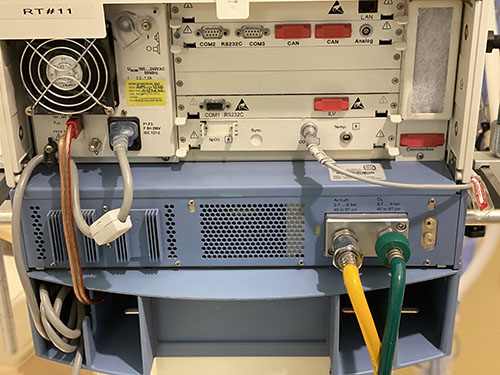
Ventilators without a turbine or compressor generally require both high pressure oxygen (green) and high pressure air (yellow) input to function appropriately, and cannot function at all without at least one of these
Ventilators with a turbine or compressor have the ability to entrain room air directly without a compressed air source; and have variable gas inputs depending on the manufacturer, including the ability to have some combination of:
- low pressure oxygen (e.g. from a portable concentrator), via common smooth bore oxygen tubing (this may require a reservoir to augment FiO2 and an adapter to connect to the device)
- high pressure (55psi/4bar) oxygen (from central pipes or a cylinder)
- high pressure air (usually not, as the turbine or compressor provides this)
Most transport ventilators are designed for continuous use for weeks or months at a time. There is scheduled preventative maintenance and the need for circuit and filter care as for any ventilator. Most of these ventilators are designed to operate for more than just a ‘transport time.’
Air-entrainment (‘Venturi’) masks can consume vast quantities of oxygen. They are designed to be used when precise control of FiO2 is needed (e.g. patients with dependence on hypoxic ventilatory drive like some COPD patients). The table below shows flow set on the Venturi (Air entrainment mask) – the total flow (O2 flow + air entrained) and the FIO2. This helps demonstrate why at low FIO2 – the Venturi mask provides a far more consistent FIO2 than nasal cannula or simple facemask. However, it should be noted that relatively high flows of 100% O2 are required to achieve high FiO2.
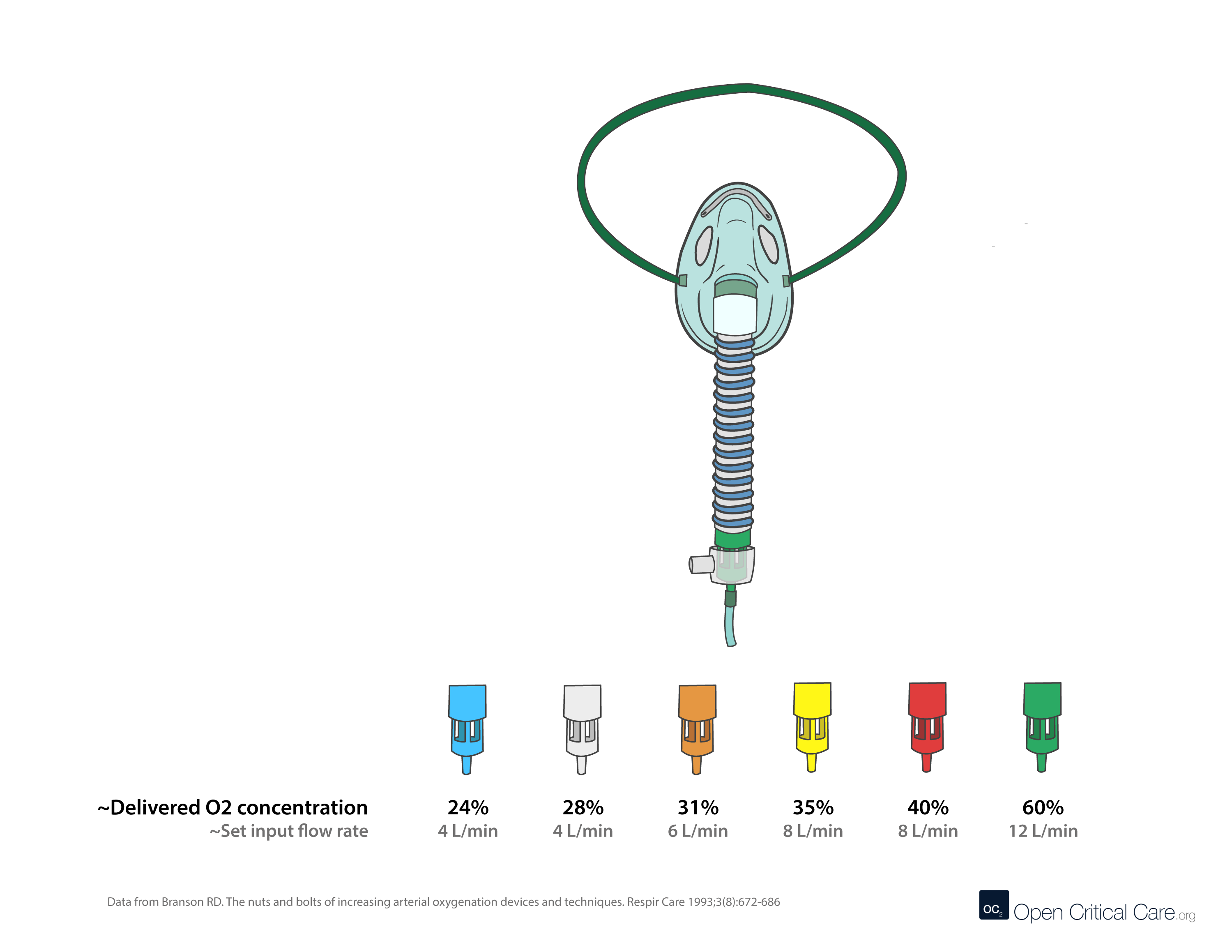
0.24
4
25:1
104
0.28
4
10:1
44
0.31
6
7:1
48
0.35
8
5:1
48
0.40
8
3:1
32
0.50
12
1.7:1
32
0.60
12
1:1
24
0.70
12
0.6:1
19
The amount of water consumed per day by active humidification depends upon several factors including minute ventilation requirements and the ability of a specific humidification system to reach and maintain the goal of providing between 33 to 44 mgH2O/L of ventilation. Under ideal conditions (use of a heated wire circuit to prevent rainout) at low (5L/min), average for critical-illness (10L/min) and high (15 L/min) minute ventilation demands, the estimated daily consumption would be approximately the following: For the gas conditioning criteria of 33-44 mgH20/L estimated H2O consumption would be approximately 250-300, 500-600 and 700-1000 mL/day, respectively.
Replace bacterial/viral filters as frequently as supplies allow in accordance with the manufacturer’s recommendations. This recommendation may be as often as every 24 hours, though the optimal interval may differ by setting and determined by assessing the risk:benefit of circuit disconnects, availability of supplies and ability to monitor for malfunctioning filters. Depending on location of the filter placement, circuit setup, humidification system and patient factors, B/V filters may function for multiple weeks, though this would be ‘off-label’ use. If an HME is used, a viral filter can be changed only with signs of increased resistance and may last a week or more. If a heated humidifier is used, the filter in the expiratory limb should be evaluated every 24 hours for signs of increased resistance and may need to be replaced every couple days, although this interval is highly variable. Always refer to the manufacturer’s recommendation. Lifespan may be significantly shortened if nebulized medications are being utilized or if copious secretions are present. Of note, disconnecting circuits can cause risk of aerosolization to healthcare workers.
Passive systems using Heat and Moisture Exchangers (HME) trap moisture and prevent it from being lost from the patient.
- Efficacy of these devices drop over time, causing increased resistance. Manufacturers may suggest a change every 24 hours, but studies have shown that an unsoiled device in some circumstances be used for several days or up to 1 week (Ricard et al, AJRCCM 2000; Thomacot et al, CCM, 2002; AARC. Resp Care. 2012).
- Signs of an increase in resistance include an increase in PIP but no change in Plateau pressure or a prolonged expiratory flow time.
- The most common cause of HME partial occlusion or rise in resistance is from pulmonary edema fluid or blood. Mucus generally clumps in a dependent portion of the device without increasing resistance appreciably. (Davis et al Crit Care Med. 2000)
Always reference the manufacturer’s recommendations as this varies. Most vents require a self test upon startup or when used on a new patient. There is additional preventive maintenance at regular scheduled intervals. All external filters should be inspected at least daily and for turbine and compressor ventilators, external inlet filters and fan filters must be cleaned at least monthly.
Many would argue that ideally, breathing circuits should be changed between new patients though do not necessarily need to be changed on a routine basis for the same patient; change the breathing circuit only if it has been soiled or damaged (Han, Liu. Respir Care 2010).
However, it is important to note:
- there is considerable practice variation on this (especially prior to the pandemic and especially with anesthesia breathing circuits); often depends on local/national regulations and patient specific factors
- circuit change practices have considerable impact on the environment
Additional Readings:
This is somewhat controversial.
For short periods of time (hours), NIPPV may be tolerated without humidity, but for longer periods of time (days) humidity is essential, especially at high FIO2 (100% oxygen from a tank or other high pressure source is ~anhydrous). Leaks with NIPPV (around a mask seal) create issues with humidification and is one reason HMEs don’t work well with NIPPV.
For HFNC, most people find >6LPM NC intolerable without humidification, but with humidification most people don’t notice flow until it exceeds 15LPM and will tolerate >40LPM. With HFNC (and nasal CPAP) gas flow is unidirectional (in the nose and out the mouth) and thus there is no possibility for reclaiming moisture from the exhaled breath. Without heat and humidification most patients will find this intolerable.
Flow triggering is a popular method for allowing patients to initiate breaths during mechanical ventilation. It works by setting a continuous “background flow” of gas through the ventilator circuit during expiration called Bias Flow. During spontaneous breathing inspiratory effort diverts some of this background flow away from the circuit to the patient. This resulting decrease in background flow exiting the ventilator is sensed and triggers an assisted breath.
Settings: The clinician sets the flow trigger sensitivity as they would pressure sensitivity. This is typically set at 1-2 L/min below the bias flow setting which may be programmed into the ventilator or can be adjusted by the clinician (e.g. 5-20 L/min). Bias flow can be a significant source of oxygen consumption.
Not all ventilators use bias flow and some have different methods of achieving flow triggering. Always refer to the product manual for device specifications.
Issues Related to Flow Triggering
Circuit Leak: If a leak develops in the circuit gas flow will be diverted away from the expiratory flow sensor causing ventilator malfunction by continuous triggering (“chattering” ) analogous to an excessive sensitivity that will impede ventilation and set-off an alarm condition.
Inappropriate Sensitivity Setting: An insensitive flow trigger level (e.g. > 5 L/min below bias flow) will increase the time delay between the onset of patient effort and the onset of the mechanical breath that often results in substantial increases in patient work of breathing and respiratory drive and patient-ventilator asynchrony. As described above, a too sensitive ventilator causes excessive triggering that can interfere with ventilation and can increase the risk of hyperinflation, barotrauma, hemodynamic instability and hyperventilation during assist-control or high levels of pressure support ventilation.
Artifacts during Indirect Calorimetry: Bias flow through the circuit interferes with the measurement of VO2 and VCO2 as it increases the total ventilation measurement by the calorimeter above the patients minute ventilation. Pressure-trigger should be used during calorimetry measurements.
Inadvertent PEEP: In some of the older ventilators that allow a high bias flow (e.g. 15-20 L/min), these flows may interact with the resistance of the expiratory block (pneumotachographs and valving) to create circuit backpressure. This would be more prominent when higher levels of PEEP are used in tandem with high bias flow. This can be easily detected when PEEP measured within the circuit exceeds the set PEEP (e.g. set PEEP = 10 and measured PEEP = 14 cmH2O).
Example Bias flow O2 consumption calculation:
For the following scenario, total oxygen consumption and oxygen consumption due to bias flow are 16.7 LPM and 6.7 LPM respectively. RR 20, TV 500, bias flow 10, leak zero, FiO2 1.0, expiratory time 2.
[Device O2 consumption rate in LPM = (Minute ventilation + (bias flow x RR x expiratory time/60) + leak) x (FiO2 – 0.21)/0.79]
Additional resources:
Ventilator Bias Flow Value Database (Coming soon)
Calculator to estimate impact of bias flow on O2 consumption
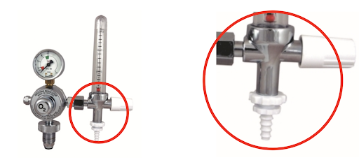
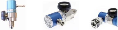
- Large J size (6800 L) oxygen cylinders (filled at 137bar/~2000psi) commonly have a Bull Nose (BS 341) oxygen outlet. Many smaller cylinders have the same outlet. Pin Index cylinders (ISO 407) may be unavailable in some resource variable settings.
- A regulator with Bull Nose connector attaches to the tank to decrease the pressure from 137bar/2200psi to ~4 bar/50psi
- Regulator outlet connectors vary (4 bar) high pressure connectors are 1/4” hose outlet, 3/8” BSP or Shrader (BS 5682) quick release (left to right in image).
- Check out our image library for oxygen connector types
- Hypoxemia is frequently defined as an arterial partial pressure of oxygen (PaO2) < 60 mmHg.
- Clinicians frequently use pulse oximeter oxygen saturation measurements (SpO2) of <90-94% to diagnose and initiate therapy for hypoxemia
- There is variability in recommendations for SpO2 goals (ranging from >88 to >94%) in the management of respiratory failure patients. There are multiple trials ongoing to elucidate the optimal strategy. SpO2 goals may have significant implications on oxygen consumption.
See chapter 6 of the WHO Severe Acute Respiratory Infection Toolkit for oxygen therapy initiation algorithms; see WFSA ANZCA Wall Chart
-
- When connected to a high pressure oxygen supply transport ventilators can deliver the FiO2, minute ventilation and pressures required to take care of most critically ill patients.
- Transport ventilators are durable and designed for use in harsh environments
- Transport ventilators usually have a turbine or compressor so that they can operate without a high pressure source of medical air. Most non-transport ventilators do not. When connected to a low pressure oxygen supply (such as an oxygen concentrator), transport ventilators may not be able to deliver the FiO2 required to take care of many critically ill patients.
- Transport ventilators are often louder (especially compressor driven vents) than non-transport ventilators. If there are multiple patients in the same room on these vents, special attention may be required for monitoring.
- Transport ventilators may have limitations in terms of monitoring and displays
- Transport ventilators usually have at least the basic modes necessary for critical care, though may have fewer features for customization than traditional ICU ventilators
- Relative to some other non-transport ventilators, transport ventilators may have limited NIV functionality (HFNC, CPAP, BiPAP functions) or may not be as good with asynchronous patients
- Transport ventilators can run without external power (for short periods of time), and without oxygen supply, or compressed air supply
- See these comparison tables of transport ventilators and non-transport ventilators by the ECRI. (Please reference the manufacturers’ manuals as the accuracy of this table is not guaranteed).
Here are some tips on how to safely conserve oxygen depending on the local context:
- Be cautious with high flow nasal cannula – high flow nasal cannula uses up to 60-70 LPM flow and can deplete stores quickly. This delivery device generally should not be used on cylinders unless a manifold system is present and a large cylinder pool is present. Additionally, even when supply may be ample, multiple HFNC devices in simultaneous use may cause system pressure failure or a rate of decline that causes excess freezing of liquid oxygen sources (which will decrease liquid oxygen output further). Always wean patient flows as quickly as possible and transition to alternative lower flow devices as soon as tolerated. There are some turbine and Venturi based devices which do not require a robust medical air supply, but these devices still consume O2 at high rates.
- Use evidence based SpO2 goals and avoid hyperoxia – Avoiding higher than necessary SpO2 goals will save vast quantities of oxygen (Read more on Optimal SpO2 Goals). The difference in SpO2 goal of 90 vs 92% in COVID19 patients can translate to 2-3x less oxygen utilized. This requires continuous or frequent pulse oximetry checks and careful, frequent titration. (see SpO2 goals). There are multiple auto-titration devices that are receiving increasing attention, but yet to see widespread use.
- Consider oxygen conserving devices – There are multiple types of oxygen conserving devices, which may or may not be useful depending on the use case. These devices include oxymizers (both pendant style and nasal reservoir style) as well as conserving devices that are placed on the cylinder directly (also known as ‘pulse dose’ devices). Reservoir-based devices conserve oxygen by enabling a higher FiO2 with lower flow rate as the patient is breathing some oxygen from the reservoir. These devices were designed to work in patients with chronic lung conditions, and their performance in patients with acute respiratory failure is largely unproven (i.e. if a patient has a higher minute ventilation). Pulse dose devices can be expensive. There are numerous other oxygen delivery devices that claim or prove oxygen conservation, however, for most of these devices performance and outcome data are lacking for acute respiratory failure patients.
- Consider liquid oxygen when possible – this is the most efficient way to store and produce oxygen, based on size:capacity. However, liquid oxygen requires considerable infrastructure on site and regionally(e.g. roads, trucks, oxygen separating plants, etc).
- Utilize additional O2 storage methods – these may be mobile liquid oxygen units, additional cylinders (Size H/J), or reservoir devices.
- Inspect and eliminate O2 system leaks – leaks in oxygen infrastructure and delivery devices are common. Common causes to include:
- Using excess flow
- Not turning off devices that not in use (e.g. anesthesia machines or flowmeters)
- Incorrectly secured fitting from cylinders
- Leaks in high or low pressure tubing due to lack of adequate maintenance
- Utilize oxygen concentrators – Consider utilizing oxygen concentrators to preserve cylinders and central supply when possible. There are multiple ways to split an oxygen concentrator to maximize the benefit of its output for multiple patients.
- Carefully adjust intentional leak for CPAP/NIPPV – properly used NIPPV/CPAP will have a leak. Too much or too little can be problematic depending on the interface and patient. Proper titration requires close monitoring and regular adjustment
- Account for Bias Flow & consider devices without bias flow – Some ventilators utilize continuous flow during the expiratory cycle – ‘bias flow.’ In some cases, this adds considerably to oxygen consumption (see ventilator settings in step 3 of this calculator) above and beyond minute ventilation consumption. See manufacturer specifications and account for this in planning.
- Consider systems that allow on-site filling of cylinder – PSA plants and deployable oxygen concentrator systems (DOCS) can be used to refill cylinders. Specifications vary widely depending on need.
- Frequent inspection and countermeasures to avoid liquid oxygen failure:
- Daily inspection to look for excess icing with increased use and colder weather, liquid oxygen evaporators may freeze – dramatically reducing O2 output. Regular inspection and countermeasures are critical (e.g. de-icing or warming systems to prevent freezing
- Inspect daily for potential leaks
- Maintain daily line pressure log and fill level
- Frequent inspection and countermeasures to avoid portable oxygen concentrator failure:
- Avoid running beyond max flow (this can cause humidity to build up in the zeolite and cause decreased efficiency and failure)
- Inspect and clean air intake filter regularly (weekly)
- Ensure functioning voltage stabilization unit if applicable
- Even when not in use, be sure to periodically turn on the concentrator for 30 minutes weekly – this will flush the system and filters of humidity which can damage the device
- Never run the unit without proper filters in place
- Keep the air intake away from walls and curtains
- Frequent inspection and countermeasures to avoid cylinder failure:
- Keep regulators and valves dust free
- Avoid (fire) ignition sources
- Ensure cylinders are stored and secured properly to prevent falling over
- Always open cylinder valves slowly
- Estimate your burn rate and plan ahead – in some settings oxygen shortages can be avoided or ameliorated by planning ahead. Keeping track of daily facility consumption and modeling surge scenarios can help with planning for production and maintenance (PSA plans), cylinder numbers needed, refill frequency (liquid oxygen). There are many tools to help with planning. The online interactive tool (below) helps quickly model ward scenarios with varying levels of detail.
- Ensure adequate power and backup power for PSA/concentrators – power failures can be a significant and abrupt cause of oxygen supply failure. If dependent on oxygen concentrators (whether portable or PSA plant), it is imperative to:
- Utilize voltage stabilization units where power supply voltage is variable
- Implement and regularly test backup power supply and/or backup cylinders in the event of power failure
Additional Resources:
Oxygen supply and demand calculator by OpenCriticalCare.org
Blakeman TC, Branson RD. Oxygen supplies in disaster management. Respir Care. 2013 Jan;58(1):173-83.
Compilation of oxygen planning tools and presentations by OpenCriticalCare.org
Frank’s Hospital Workshop Tutorials – Oxygen Concentrators – by Frank Weithoner
Oxygen conservation infographic – Branson et al, CHEST, May 2021
- It depends on the device setup. Ventilators may require ‘external’ filters (viral, HME, and fan, as well as air intake filters for turbine or compressor ventilators) and internal filters (oxygen inlet filter). Filters can provide three kinds of functions:
-
- Filtering particulate matter
- HEPA (high-efficiency particulate air) filters rated to 3 microns are generally considered ‘acceptable’ for bacterial and viral filtration. The term HEPA refers to the efficiency of capturing particles with a MPPS (most penetrating particle size) diameter of 0.3 microns.
- Of note, machines that accept 50psi/4bar gas intake usually have internal bronze sintered filters to protect the machine from contaminated gas sources. On occasion additional external filters on the high pressure gas lines are required to prevent damage to the device.
- Preserving heat and moisture
- Heat and Moisture Exchangers (HME) are commonly rated to 3 microns, the HEPA standard (and may be referred to as HME filters – HMEF), but may not be. They are composed of foam, paper or other material that allows moisture to condense.
- Hygroscopic Condenser Humidifiers (HCH) are functionally the same as HMEs, though have a slightly different mechanism as they are impregnated with a salt to aid in moisture condenstation. In the past, HME types were separated based on the additional treatment of the media. An HME relied solely on physical principles (the earliest ones were all aluminum) whereas the HCH included treatment of the media with a hygroscopic salt (LiCl, now mostly CaCl). At present, the reality is that most HME devices also take advantage of the hygroscopic salt (check manufacturer’s specifications to confirm this). In theory, if one were to push the media out of an HME then touch it to the tip of the tongue – it would be very salty (DO NOT TRY THIS).
- The moisture efficiency of an HME or HCH is dependent on its size, media density and salt treatment.
- HMEs may be referred to as type I (adult) and type II (pediatrics), which differ in deadspace and functional tidal volume range.
- Unless specifically designated as having capacity for ‘filtration’ (HMEF), HMEs do not provide adequate filtration of bacteria and viruses.
- Filtering bacteria and viruses
- Bacterial/viral (B/V) filters are defined by the ability to filter particles with a diameter size of 3 microns though may be rated to particles as small as 0.2 microns, and do not necessarily provide heat/moisture preservation.
- The minimum viral filtration efficiency (VFE) that is needed to ensure SARS COV-2 virus can not pass from the patient to the room or machine is unknown.
- B/V filters with 99.97% ASTM efficiency or filters with >95% efficiency for MPPS of 0.3 microns may be recommended to prevent SARS-CoV-2 viral transmission though data and standards continue to evolve.
- Diameter for SARS-CoV-2 virion is ~0.06-0.14 microns, hepatitis C is 0.03 microns and Staph aureus is 1 micron.
- Filtering particulate matter
- Combination filters providing all three functions are available. Filters that conserve heat and moisture and provide B/V filtering are often referred to as HMEF.
- More info on filter types and efficiency testing
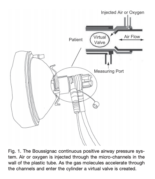
- Boussignac is a low cost, easy to use facemask CPAP-like system that has no sensors, mechanical valves or electrical components. The system connects to an oxygen flowmeter/source that generates flow dependent pressure (8LPM ~3cmH20; 15LPM ~5cmH20; 23LPM ~10cmH20)
- Traditionally used by prehospital providers for cardiogenic pulmonary edema
- In patients with hypoxemic respiratory failure (non cardiogenic pulmonary edema), it is unclear if this device would work well in patients with high minute ventilation (Sehlin et al, Resp Care, June 2011).
- There are several noteworthy potential limitations:
- Utilizes high oxygen flows
- Limited ability to adjust FiO2
- At high flows will cause airway dryness and discomfort.
- No leak compensation
- No monitoring of pressures
The term transport ventilator can refer to a wide range of ventilators in terms of capability. Generally, the term ‘transport’ refers to the capability to use the ventilator for transporting patients during which time central power and pressurized gas supply may be limited. These ventilators usually have robust internal battery backups and the ability to function without a high pressure gas supply (e.g. they include a turbine or compressor to entrain room air to drive the ventilator). Most can also operate with either high or low pressure oxygen input. Many transport ventilators are designed to care for intensive care unit patients (See WHO Technical Specifications for Ventilators).
It depends on several factors. Not all masks, circuits or devices are compatible or able to deliver CPAP/NIPPV.
The basis of non-invasive CPAP/NIPPV is a constant gas flow against an expiratory resistor that creates positive “back pressure” in the circuit (i.e. Pressure = Flow x Resistance). Back pressure is increased either by increasing gas flow against the resistor or increasing the resistance to gas flow.
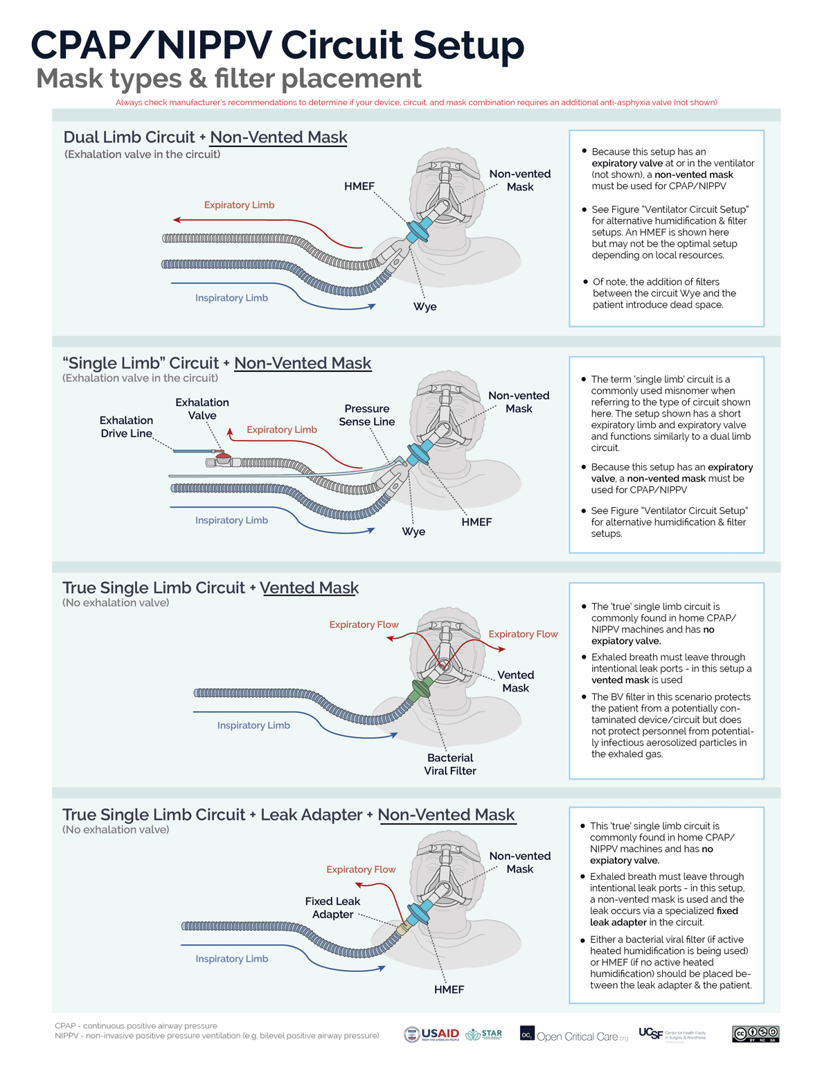
There are 2 circuit options for non-invasive CPAP (or NIPPV/BiPAP):
- A “true” single limb circuit (commonly found in home NIPPV/BiPAP devices) has 1 hose directing gas from the device to the mask and no active expiratory valve. There are two common setups for NIPPV/CPAP with a true single limb circuit. (Note: circuits with both an inspiratory limb and a short expiratory limb with expiratory valve, while commonly referred to as ‘single limb’ are not ‘true’ single limb circuits)
- “Vented Mask” setup – The exhaled breath has to get out of the patient/circuit somewhere, therefore, the mask must act both as the resistor and the exhalation port. A vented mask has holes that allow for fixed resistance. Because the resistance is fixed, CPAP is increased by increasing flow through the circuit.
- Fixed leak valve circuit setup – An alternative option to using a vented mask, is to use a non-vented mask and to place the fixed/intentional leak into the circuit by adding a ‘leak valve,’ which contains holes that allow fixed resistance.
- A dual limb circuit (commonly found in ICU and transport ventilator) has 2 hoses connected by a “Y” (or “wye”) adapter where the expiratory limb directs gas flows to an active expiratory valve that controls expiratory resistance. The expiratory valve either is clearly visible in the expiratory hose (“expiratory manifold”) or the expiratory hose attaches directly back into the ventilator (i.e. the expiratory manifold is built into the ventilator). To function properly (ie to create/adjust CPAP, or pressure-support/ BiPAP) the circuit must only be used with a non-vented mask (i.e. the ventilator will control both gas flow and resistance).
- Troubleshooting Note: Using a vented mask with any dual limb ventilator circuit will result in the inability to effectively create sufficient positive pressure, increased aerosolization and likely set-off alarms.
Some ventilators can utilize both true single limb and dual limb setups. Another approach to determine the correct mask type for NIPPV/CPAP is to determine if the system (ventilator or circuit) has an an active exhalation valve:
- System with active exhalation valve – non-vented mask required
- System without active exhalation valve – vented mask required (or fixed leak adapter in the circuit)
When access to optimal equipment is not readily available, alternative solutions (https://link.springer.com/article/10.1007/s41782-020-00092-7) have been proposed and reported with uncertain outcomes. These are most often not in line with manufacturers’ recommendations and are not endorsed here. Always check manufacturer recommendations for all devices to confirm correct equipment and mode settings.
Continuous Positive Airway Pressure (CPAP) devices or modes apply constant pressure throughout the respiratory cycle via face mask or other interface to splint open the upper airway, increase lung volume, and increase intrathoracic pressure. CPAP provides no inspiratory muscle unloading and tidal ventilation remains completely dependent on the respiratory muscles.
Non-invasive ventilation (NIV) or Non-invasive positive pressure ventilation (NIPPV) applies two levels of pressure during the respiratory cycle – a pressure during the inspiratory phase that is greater than the pressure applied during exhalation. This is effectively mechanical ventilation, and can unload the respiratory muscles and provide complete respiratory support.
Bilevel positive airway pressure (BIPAP) is a branded/trade name (by Phillips) for NIPPV/NIV as described above
Estimated Fraction of Inspired Oxygen (FiO2)
Nasal Cannula
1
0.24
-
2
0.28
-
3
0.32
-
4
0.36
-
5
0.40
Simple Facemask
6-10
0.44-0.50
Non-Rebreather Mask with Reservoir
(reservoir must be fully inflated)
10-20
Approx 0.6-0.8
At RR ~20 & Tidal Volume ~500
20 LPM flow = ~60% FiO2
30 LPM flow = ~70% FiO2
40 LPM flow = ~80% FiO2 (Farias et al).
The values represent estimates of FiO2. Actual FdO2 (delivered O2 concentration) is dependent on multiple factors including oxygen supply quality, patient’s minute ventilation and inspiratory flow rate. One general estimation rule is using oxygen flow rate: FiO2 =0.21 + 0.03 x oxygen flow rate in L/min (Frat et al).
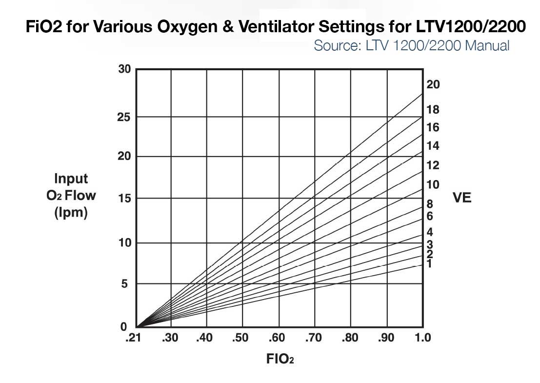
- The short answer is that it depends on many factors and varies by ventilator model (so check the manufacturers’ specifications)
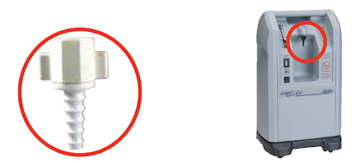
- Some ventilators like the LTV 1200/2200, PB560 and Zoll 731 can run off of a low pressure oxygen supply. They utilize 21% ambient air from the room via a built in compressor or turbine and mix that with the low pressure oxygen input.
- When utilizing low flow oxygen, ventilators usually will not allow you to use the blender – i.e. you can’t set the FiO2
- Concentration of oxygen delivered to the patient (FiO2) is determined by: minute ventilation, flow of oxygen supply into the vent, concentration of oxygen supply into the vent, and potentially other factors.
- For example:
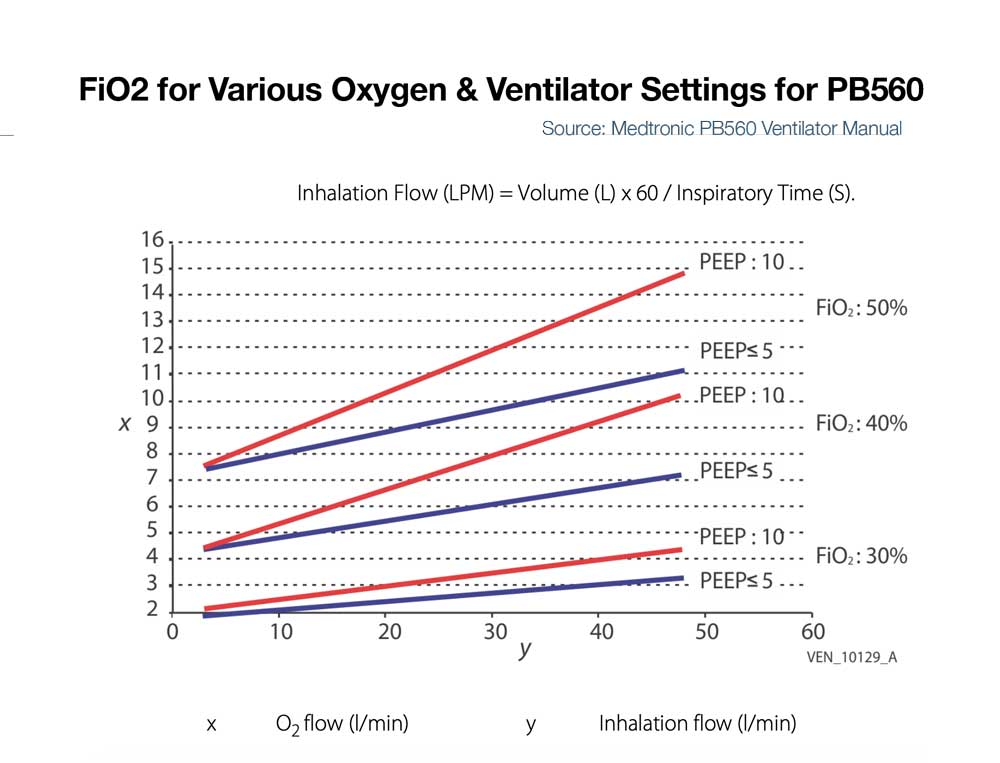
- LTV 1200/2200 – If input flow is set to minute ventilation, then the LTV1200/2200 can deliver ~100% FiO2 up to ~20LPM minute ventilation. For a patient with 10 LPM minute ventilation and 5 or 10LPM input low pressure oxygen, max FiO2 delivered to the patient is approximately 50 and 75% respectively. (See Figure below left)
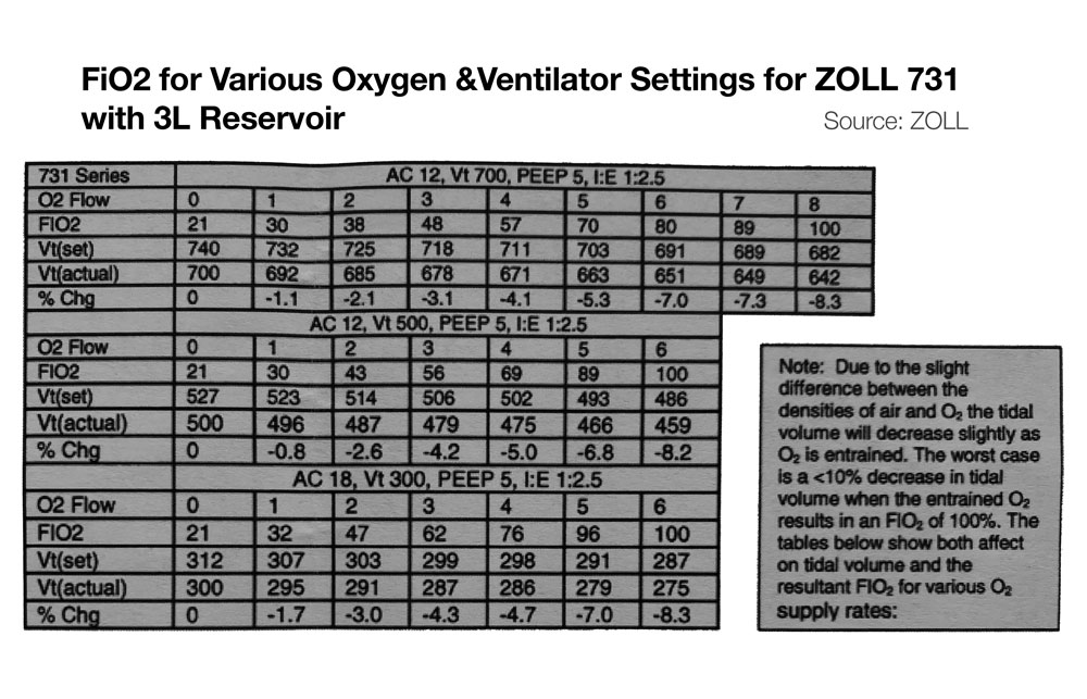
- Zoll 731 – If input flow is set to minute ventilation, and an external reservoir (e.g. ZOLL 731) is used on the compressor intake, then FiO2 of ~100% is possible on the Zoll 731 for minute ventilation up to ~20 LPM. (See Figure below, bottom) For more information on using the ZOLL 731 with low pressure O2 sources see the users manual and this quick reference.
- PB560 – Some ventilators like the PB560 that only accept low flow oxygen may be limited in the amount that can be delivered into the device at low pressure and thus be limited in FiO2 delivery to the patient (e.g. the PB 560 is designed to deliver a percentage of oxygen equal or lower than 50%. Exceeding this value may cause the ventilator to malfunction and put the patient at risk). (See Figure below right)
- Of note, 50% FiO2 is approximately equivalent to that delivered by a simple facemask at 10LPM (Read more about FiO2 delivered by various oxygen delivery devices)
- When using low pressure oxygen supply for devices with bias flow (flow during the expiratory time) and/or during NIV modes with leak compensation, the FiO2 can be diluted significantly.
- When using low pressure oxygen supply, you likely will need to change the ventilator setting to indicate such a source is being used (e.g. ‘reservoir mode’ or ‘low pressure input’)
- Due to slight difference in the densities of air and O2, tidal volume may decrease slightly as FiO2 increases via low pressure entrainment. See manufacturer’s specifications, though generally this would be expected to be less than 10% change in tidal volumes.
It depends on the positive pressure device and circuit being used. If a single limb circuit without an active exhalation valve is being used (e.g. a home NIPPV machine), then a vented mask or vented circuit must be used (i.e. fixed orifice resistor outlet). If a dual or single limb circuit with an active exhalation valve is being used, then an NIV mask without a vented port should be used. Read more on circuit and mask setup for NIPPV/CPAP
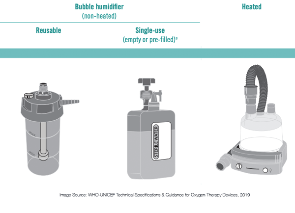
- Passive systems:
- Non-heated bubble humidifiers – are simple, low cost devices used with low flow oxygen delivery devices like nasal cannula or nasopharyngeal catheters. These devices require sterile or distilled water and are generally not efficient. Some may be reusable or single-use only.
- Heat and Moisture Exchangers (HME) are simple, low cost components used with mechanical ventilators and CPAP or NIPPV devices. HMEs trap moisture and prevent it from being lost into the ventilator. They are not reusable.
- Efficacy of these devices drop over time, causing increased resistance. Many manufacturers suggest a change every 24 hours, but studies have shown that an unsoiled device in some circumstances can be used for several days (Ricard et al, AJRCCM 2000; Thomacot et al, CCM, 2002).
- Signs of an increase in resistance include an increase in PIP but no change in Plateau pressure or a prolonged expiratory flow time.
- The most common cause of HME partial occlusion or rise in resistance is from pulmonary edema fluid or blood. Mucus generally clumps in a dependent portion of the device without increasing resistance appreciably. (Davis et al Crit Care Med. 2000)
- Read more about how often HMEs should be replaced
- Hygroscopic Condenser Humidifiers (HCH) are functionally the same as HMEs (though have a slightly different mechanism). In the past, HME types were separated based on the additional treatment of the media. An HME relied solely on physical principles whereas the HCH included treatment of the media with a hygroscopic salt (LiCl, now mostly CaCl). An HME may be made from foam, paper or other substance that helps water condense (the earliest were aluminum). At present, the reality is that most HME devices also take advantage of the hygroscopic salt (check manufacturer’s specifications to confirm this). In theory, if one were to push the media out of an HME then touch it to the tip of the tongue – it would be very salty (DO NOT TRY THIS). The moisture efficiency of an HME or HCH is dependent on its size, media density and salt treatment. HMEs may be referred to as type I (adult) and type II (pediatrics), which differ in deadspace and functional tidal volume range.
- Active systems:
- Active heated humidification systems use a reservoir of water and a heating element. Inhaled air is typically passed through this heated chamber to become humidified before it enters the patient. Ideally, the inspiratory limb of the circuit contains a heating element to preserve the heat and humidification and to keep excess water from condensing and pooling in the circuit.
- These systems require power, a supply chain for sterile or distilled water, and additional disposable tubing.
- Active heated humidification systems use a reservoir of water and a heating element. Inhaled air is typically passed through this heated chamber to become humidified before it enters the patient. Ideally, the inspiratory limb of the circuit contains a heating element to preserve the heat and humidification and to keep excess water from condensing and pooling in the circuit.
Elimination of a machine mounted inspiratory filter – If a bacterial viral filter is used between the circuit Wye and the patient, then an additional inspiratory filter between the machine and the inspiratory limb may not be necessary to protect the patient (so long as the machine is kept clean and an airway mounted filter and/or expiratory limb filter is used). That is a big “if,” and the use of an inspiratory limb filter at the circuit takeoff is to eliminate this chance of error.
A single inspiratory filter setup (at the wye) has been suggested as an option in settings of severe shortage. This setup may create potential for error and subsequent contamination of the machine. Additionally, the use of one instead of two filters in series significantly decreased viral filtration efficiency. The impact on risk of viral contamination is unknown.
Expiratory limb filter extended use (i.e. not changing between patients) has been suggested by some as an option if severe shortage is faced and appropriate bacterial viral filter is used at the patient. APSF
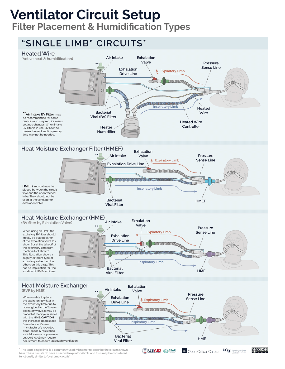
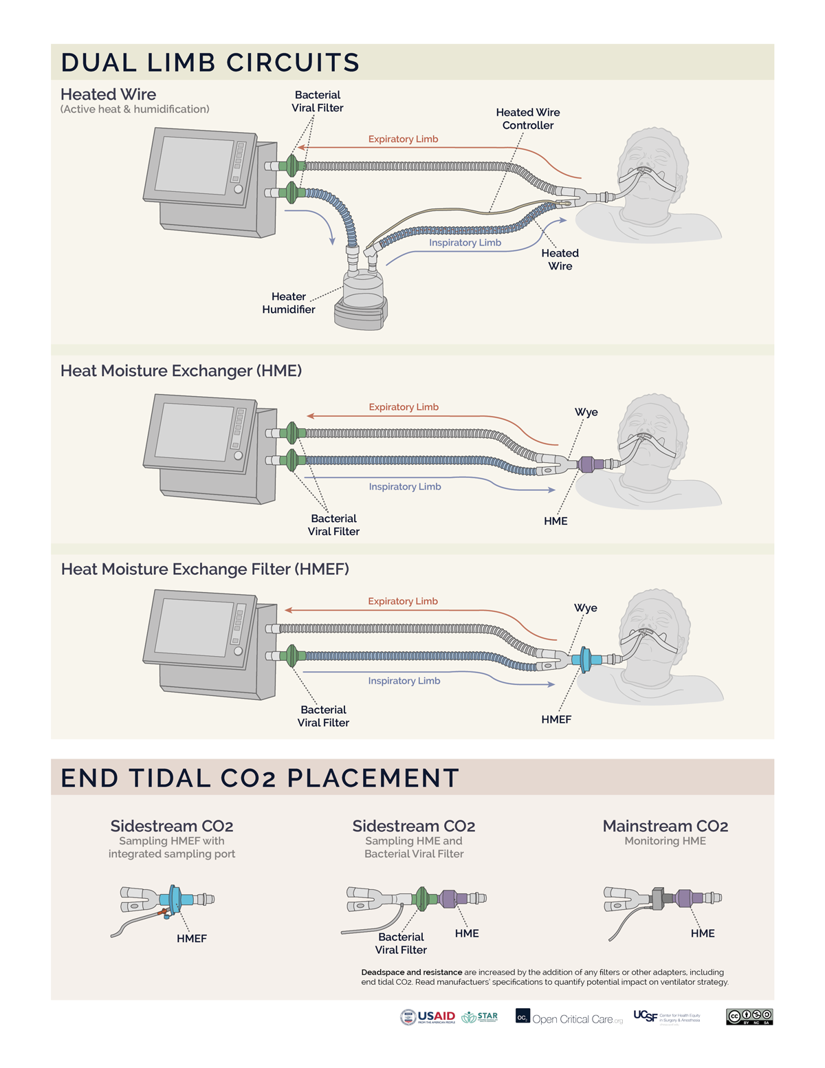
- Filters may be placed at the air intake, inspiratory limb, patient Wye, expiratory limb and/or exhaust port, however, placement at each of these sites does not provide equivalent function. (Video of filter placement location)
- Ideally a two filter setup should be used (Anesthesia Patient Safety Foundation):
- Inspiratory/Patient filter: the first filter should be placed between the circuit Wye connector and the patient and achieves two things: 1) protects the ventilator and the room from exhaled gases from an infected patient, 2) protects a non-infected patient from a possibly contaminated ventilator. If using an active heat and humidification system, then this should be a bacterial viral filter (not an HME). If not using active heat and humidification, then this should be an HMEF or a bacterial viral filter in series with an HME (HME should be between endotracheal tube and B/V filter). In a dual-limb ICU ventilator, the inspiratory bacterial viral filter may be placed on the inspiratory limb at the takeoff from the ventilator.
- Expiratory filter: A second bacterial viral filter is recommended on the exhalation limb before the exhalation valve, to protect the room environment and healthcare staff from stray particles (and to protect the device in a dual limb circuit setup).
- Placement of filters between the circuit Wye and the patient’s endotracheal tube can add significant deadspace to the circuit, especially for pediatric patients.
Click here to download high resolution version of the images below
Moisture present in patients’ lungs is rapidly lost at high breathing rates.
When breathing dry air, cilia stop functioning properly (in a matter of hours – Hirsch et al J Appl Physio 1975). When the moisture level becomes low, mucous in the patient’s lungs can become thick and hard, and quickly block the patient’s airways, or the endotracheal tube, stopping airflow.
Additionally, heat is rapidly lost to non-humidified air.
Relatively simpler devices (e.g. transport ventilators) ’sense’ oxygen input as the presence of a high pressure inlet gas – but does not measure actual oxygen concentration (FIO2). So long as the input pressure was adequate, many devices could not discern whether the concentration of oxygen input is adequate (i.e. 93-99%).
The more sophisticated and newer ICU ventilators and anesthesia machines have internal O2 analyzers. If these devices are connected to a gas input that is of adequate pressure but low oxygen concentration, they may either alarm or not function properly. The alarm may have to be disabled but this will vary by manufacturer.
In summary, if you connect a source of oxygen with low concentration, some ventilators may have no idea and not alarm, but other ventilators may sense this and not function properly or alarm (which you may or may not be able to disable).